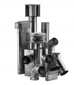
DuraVent – Venting Industry Leader

Type B Gas VenB-VENT
Round Gas Venting
DuraVent’s innovative system of a lock-tight connection for Type B Gas Vent called DuraLock. See the alignment indicators meet; feel the ends grasp together; hear the snap as the connection firmly locks into place.

Type B gas vents are not suitable for use with wood-burning or coal applications, industrial ovens, exhaust ranges and hoods, grease or pollution ducting, or as free-standing exhaust vents for high-temperature applications. 

Applications
DuraVent’s Type B Gas Vent system. Use with natural gas or liquid propane category I and draft hood equipped appliances, and appliances tested and listed to use Type B Gas Vent. Applications include: natural gas fireplaces, gas-fired furnaces, boilers, water heaters, and wall or space heating applications.

Materials and Construction
Round Type B Gas Vent 3″ – 8″ : Aluminum .012″ inner wall, galvanized .018″ outer wall. 3″-8″ diameters feature twist-lock fittings.

Clearances
1″ clearance to combustibles in single and multi-family dwellings.

Diameters
3″- 8″ Round Diameter.

Listings
UL Listed to UL 441 and UL 1777 (MH6357). ULC Listed to ULC S605 (CMH1276 & CMH1407).

Warranty
Limited Lifetime Warranty

Refer to our Typical Venting Installation drawings to select the appropriate component parts for your installation.

More Typical Installations:

Installation Key
1DuraCap
2Storm Collar
3Roof Flashing
4High-Wind Cap
5Round Pipe
6Elbow
7Tee
8Tee Cap
9Increaser Tee
10Female Flex Adapter
11Male Adapter
12Double-Wall Wye
13Pipe Collar
14Increaser
15Draft Hood Connector
16Square Firestop Support
17Oval Pipe
18Oval to Round Adapter
19Oval Tee
20Oval Tee Cap
21Oval Tee Support
22Oval Firestop Spacer
23DuraConnect II
24DuraFlex AL Length
25DuraFlex Motar Sleeve
26DuraFlex AL Coupling
 

How Size and Height Affect Stove Performance

  • The amount of heat the vent gases lo0se as they flow determines how much condensation will occur and how strong the draft will be. To control the heat loses, proper selection of venting materials is of vital importance.
  • Double-wall Type B Gas Vent, with an aluminum inner wall and a galvanized steel outer wall, has proven to be the ideal choice in venting materials.

Vent Termination Chart
Using listed Type B Gas Vent caps may terminate in accordance with this table.

Minimum height
Roof PitchFeetMeters
Flat to 7/1210.30
Over 7/12 to 8/121.50.46
Over 8/12 to 9/1220.61
Over 9/12 to 10/122.50.76
Over 10/12 to 11/123.250.99
Over 11/12 to 12/1241.22
Over 12/12 to 14/1251.52
Over 14/12 to 16/1261.83
Over 16/12 to 18/1272.13
Over 18/12 to 20/127.52.29
Over 20/12 to 21/1282.44

Gas Vent Specification Chart

ItemClearancesMaximum HeightOuter Tube ØMaterialsLocking DeviceUL ListingULC Listing
Type B Vent Round 3″-8″1 inch to combustibles100 feet5/8″ larger than IDInner – .012″ Aluminum Outer – .018″ GalvanizedDuraLockMH6357CMH1276
Round 10″ to 16″ See note 21 inch to combustibles100 feet1″ larger than IDInner – .016″ Aluminum Outer – .021″ GalvanizedTwistLock ScrewsMH6357CMH1276
Round 18″ to 30″1 inch to combustibles100 feet2″ larger than ID See note 5Inner – .020″ Aluminum Outer – .021″ GalvanizedScrewsMH6357CMH1276
Oval Type B Vent 4″ and 5″2″ x 4″ & 2″ x 6″ stud wall and 1 inch to combustiblesSee Note 32 1/2″ x 7 1/4″ 3 1/8″ x 10 7/8″Inner – .012″ Aluminum Outer – .018″ GalvanizedButton LockMH6357CMH1276
Oval Type B Vent 6″2″ x 6″ stud wall and 1 inch to combustiblesSee Note 33 1/4″ x 12″Inner – .012″ Aluminum Outer – .018″ GalvanizedButton LockMH6357CMH1276
Type B Vent 3″ to 6″ Round Liner”0″/Masonry50 feet5/8″ larger than IDInner – .012″ Aluminum Outer – .018″ GalvanizedDuraLockMH14420 MH6357CMH1407
DuraFlex AL Gas Relining 3″ to 6″0″/Masonry50 feet1/4″ larger than ID.010″ Aluminum FlexScrews DuraLockMH14420
DuraConnect 3″ to 6″1 inch to combustiblesSee Note 41/4″ larger than ID.010″ Aluminum Flex .018″ GalvalumeDuraLockMH14089
DuraConnect II 3″ to 6″1 inch to combustiblesSee Note 41/4″ larger than ID.010″ Aluminum Flex .018″ GalvalumeDuraLockMH14089

Note:

  1. Clearance to combustibles is the air space between vent and combustibles.
  2. Maximum height varies with equipment over 50′, for taller applications refer to SDV sizing handbook (L202). 14″-16″ Pipe require screws.
  3. When oval is used on wall furnaces, minimum height required from bottom of furnace to cap is 12′, minimum 16″ stud space.
  4. Limited by sizing tables.
  5. 18″ pipe OD is one inch larger than ID and 20″ – 30″ OD is 2″ greater than ID.
Let Us Help!